
Overview
This walkthrough explains how to start from scratch, conceive a small architecture, and implement that architecture using ArchStudio 3 and xADL 2.0 tools. Certainly, this is not a comprehensive guide to these tools and technologies, but it will get you familiarized with them and serve as a starting point for more involved development.
Note that this document mostly covers developing software with ArchStudio 3, as opposed to developing extensions to the ArchStudio 3 environment itself. Also note that, as a user of the ArchStudio 3 and xADL 2.0 tools, you can use a few of these tools or a lot of them, depending on how much of the underlying approach you "buy into." This document will attempt to highlight any assumptions that are being made as it progresses.
Project Overview
Our project for this walkthrough will be to build a small client-server chat system, sort of like an Instant Messaging client. For simplicity, the system will run on a single machine in a single process, with a fixed set of 2 clients. Clients will have a small GUI that displays a chat transcript and allows the user to enter and send short text messages. The server will be a simple broadcast server, relaying any messages from any one client to all clients in the system.
Assumptions: The rest of this tutorial assumes that you have installed the xArch/xADL 2.0 Data Binding Library, ArchStudio 3, and a Java development environment, and have familiarized yourself with these tools.
Step 1: Architecture
Of course, now that our requirements are laid out, the first thing to do is to decide on an architecture for our chat system. To define an architecture, it helps to decide on an architectural style. For this project, we will use the C2 architectural style. The C2 style is a natural fit for this project because all communication will be done by simple, discrete text messages that can be sent any time (asynchronously). The layered nature of the C2 style fits well with the two-tier client/server system that we are developing. While we will choose the C2 style for this project, building in a generic client/server style (that uses RPC or oneway procedure calls, for instance) would be extremely similar.
For the unfamiliar, we will quickly review the key constraints of an event-based architectural style such as C2:
- Components only communicate using asynchronous events.
- Components may only communicate via explicit software connectors. That is, an implicit connector like a file in the filesystem is not allowed.
- Events, or messages, must not contain pointers (i.e. they must be serializable/marshalable).
- Corrolary: No assumption of shared memory among components.
- A component may do anything it wants inside the component.
The C2 style induces a few additional topological constraints:
- Each component or connector has exactly two interfaces, designated 'top' and 'bottom'
- Components may have at most one connection on the top and one one the bottom. If a component is connected to something, it must be a connector.
- Connectors may have any number of components or connectors connected to their top or bottom interface.
- There are no cycles allowed in the connectivity graph (i.e. a layered style is explicitly induced.)
So, our architecture for the client-server chat system in C2 will look roughly like this:
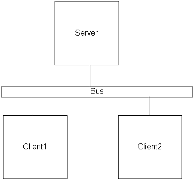 |
| Architecture in C2 |
Now that we have a general boxes-and-arrows feel for our architecture, we need to decide on some details:
Interfaces: Because this is a C2 style architecture, each component and connector (collectively referred to as bricks) will have exactly two interfaces: a top interface and a bottom interface. Bricks have these interfaces in C2 whether anything is connected to them or not. C2 interfaces have essentially two duties: to send messages and to receive messages. All C2 interfaces are identical in this regard.
Types: From this architecture, we see that we have 3 components (Server, Client1, and Client2) and one connector (Bus). However, the Client1 and Client2 components should have exactly the same behavior (that is, they are two instances of the same code). Thus, we can infer that Client1 and Client2 are both of the same component type. The Bus and Server each have their own type, since no other brick in the architecture shares their behavior. However, if we were to add a middle tier, containing an obscenity filter for example, there might well be a second bus of the same connector type as the first. Assumption: Bricks that share a type share an implementation.
So, now we have to describe the architecture in the xADL 2.0 architecture description language. We will leverage xADL 2.0's modularity here by only describing the architecture in enough detail to implement and instantiate it. Advanced xADL 2.0 features like product line architecture support will be out of scope for this project.
For xADL 2.0 descriptions of architectures in this walkthrough, we will use the abbreviated format used throughout the xADL 2.0 Distilled guidebook. While this is not "real" XML or xADL 2.0, it is the only way to make the descriptions readable here.
This architecture, consisting of only four bricks and three types, is relatively simple. With the current ArchStudio 3 toolset, there are basically three ways to create an architecture such as this one:
- Create with ArchEdit: You can use ArchStudio 3's syntax-directed xADL 2.0 editor, ArchEdit, to create the architecture from scratch by adding each element necessary and filling in the details. This process is relatively tedious for large architectures, but is practical for small architectures such as ours here.
- Modify an existing description in ArchEdit: ArchStudio 3 already ships with several architecture descriptions for C2-style systems (including the description of ArchStudio 3 itself). It is feasible to use ArchEdit to modify a copy of one of these descriptions to suit another architecutre, although for an architecture of this size, the amount of effort required to do this is nearly equivalent to the amount of effort it takes to create a description from scratch.
- Create with a Java program: The xArch/xADL 2.0 data binding library
provides a flexible way to create and manipulate architecture descriptions from
Java programs. Use of parameterized methods in Java can reduce the redundancy
associated with creating detailed architecture descriptions. This method is
practical for creating architecture descriptions of sizable systems, and in fact
is the method used to create the description for ArchStudio 3 itself. For this
project, it would be wise to take an existing description-creator program, such
as the
archstudio/Description.javafile in the source distribution, and modify it to suit this architecture.
NOTE: Unfortunately, at this time there are no graphical editors (i.e. box-and-arrow style editors), including Visio for xADL, that are mature enough to use for creation and maintenance of architectures in ArchStudio 3. Please contact Eric Dashofy about development of graphical editors for xADL 2.0/ArchStudio 3.
Regardless of the approach taken, this walkthrough will address the contents
of the xADL 2.0 document that need to be created, using abbreviated non-XML
notation for simplicity. NOTE: In this
walkthrough, the xsi:type (XML schema instance type) of an element
will only be explicitly specified when a subtype is being used in place of the
specified type in the parent element's definition.
Along with this example, a Description.java file is included in the
ArchStudio 3 distribution, as src/c2demo/chatsys/Description.java.
This Description file is an example of how to create the following description
using a Java program, as described above. The resultant xADL 2.0 description
is also included in bin/chatsys.xml, which is generated using
chatsys.Description.
First, we will model the component, connector, and interface types to create a "type library" that we can use when describing our architecture's topology. Let's start by defining the interface types for a C2 architecture. Because we are going to implement this architecture in the c2.fw framework, we will add some implementation information that corresponds to the use of that framework.
xArch{
  archTypes{
    //ArchTypes definition specifies that
    //archTypes element can contain InterfaceTypes,
    //here we use a subtype (InterfaceTypeImpl) to
    //specify an interface type with implementation.
    interfaceType xsi:type=InterfaceTypeImpl{
      (attr) id   = "C2TopType"
      description = "C2 Top Interface Type"
      implementation xsi:type=JavaImplementation{
        mainClass{
          //Use the basic c2.fw interface implementation
          //for this interface; in reality this data is
          //ignored by the runtime infrastructure now
          //but may be used in the future.
          javaClassName = "c2.fw.SimpleInterface"
        }
      }
    }

    interfaceType xsi:type=InterfaceTypeImpl{
      (attr) id   = "C2BottomType"
      description = "C2 Bottom Interface Type"
      implementation xsi:type=JavaImplementation{
        mainClass{
          javaClassName = "c2.fw.SimpleInterface"
	    }
      }
    }
  }
}
|
Note that, for this architecture, we have chosen to model only two types of interfaces: tops and bottoms (which are basically the same). In reality, the services provided/required by actual component interfaces are more complex and involve various message protocols. However, the current ArchStudio 3 toolset does not include tools that are capable of doing protocol analysis at this level, so specifying the interfaces in more detail is not necessary or useful at the architectural level. If, in the future, such analysis tools become available, the xADL 2.0 description can be extended and refined to work with them.
Now that we have defined all the interface types for our architecture, we can focus on defining the component and the connector types in much the same way. We are actually adding to the previous document; new bits will appear in blue.
xArch{
  archTypes{


    //Note: this has to be a VariantComponentTypeImpl
    //because XML schema does not support multiple
    //inheritance.  Thus, we introduced a small
    //artificial dependency, whereby component types
    //with implementations extend VariantComponentType.
    //The fact that this is a VariantComponentType
    //only means that the component type *CAN* have
    //be variant, not that it *WILL* be variant.

    componentType xsi:type=VariantComponentTypeImpl{
      (attr) id   = "Server_type"
      description = "Server Component Type"
      implementation xsi:type=JavaImplementation{
        mainClass{
          javaClassName = "chatsys.ServerC2Component"
        }
	  }
    }

    componentType xsi:type=VariantComponentTypeImpl{
      (attr) id   = "Client_type"
      description = "Client Component Type"
      implementation xsi:type=JavaImplementation{
        mainClass{
          javaClassName = "chatsys.ClientC2Component"
        }
      }
    }

    connectorType xsi:type=VariantComponentTypeImpl{
      (attr) id   = "Bus_type"
      description = "Bus Connector Type"
      implementation xsi:type=JavaImplementation{
        mainClass{
          //This is a provided class in the c2.fw
          //framework:
          javaClassName = "c2.legacy.conn.BusConnector"
        }
      }
    }


    //ArchTypes definition specifies that
    //archTypes element can contain InterfaceTypes,
    //here we use a subtype (InterfaceTypeImpl) to
    //specify an interface type with implementation.
    interfaceType xsi:type=InterfaceTypeImpl{
      (attr) id   = "C2TopType"
      description = "C2 Top Interface Type"
      implementation xsi:type=JavaImplementation{
        mainClass{
          //Use the basic c2.fw interface implementation
          //for this interface; in reality this data is
          //ignored by the runtime infrastructure now
          //but may be used in the future.
          javaClassName = "c2.fw.SimpleInterface"
        }
      }
    }

    interfaceType xsi:type=InterfaceTypeImpl{
      (attr) id   = "C2BottomType"
      description = "C2 Bottom Interface Type"
      implementation xsi:type=JavaImplementation{
        mainClass{
          javaClassName = "c2.fw.SimpleInterface"
	    }
      }
    }
  }
}
|
This concludes the description of the types for our architecture. Now, we have defined a set of types for our architecture and mapped them to implementations of those types (some of which already exist, as provided by our target implementation framework, and some that we have to write ourselves). The next step is to create structural elements of these types and link them up in a topology.
In xADL 2.0, the design-time structure of the architecture is specified
in descendants of the archStructure tag. Even though the
components and connectors that will be specified here are technically
instances of the types we defined above, we will not use the constructs
in the xArch (instance) schema for modeling design-time architectures;
the instance schema is used in xADL 2.0 to model run-time instances.
ArchStudio 3 can create an instance model of a running system when
necessary.
So, we will add to the description above and create the topology of the architecture. First, we'll create the components and connectors, and use XLinks to link them to their types, as specified elsewhere in the document.
xArch{

  archStructure{

    component{
      (attr) id   = "Server"
      description = "Server Component"

      interface{
        //Note that the convention used by the c2.fw runtime
        //infrastructure is to preface interface IDs with
        //the name of the brick and a period (dot)
        (attr) id = "Server.IFACE_TOP"
        description = "Server Top Interface"

        //C2 interfaces are always inout because they pass
        //messages both ways
        direction = "inout"

        //Link interfaces to their types as well
        (link) type = "#C2TopType"
      }

      interface{
        (attr) id = "Server.IFACE_BOTTOM"
        description = "Server Bottom Interface"
        direction = "inout"
        (link) type = "#C2BottomType"
      }

      //Use an XLink to link to the type
      (link) type = "#Server_type"
    }

    component{
      (attr) id   = "Client1"
      description = "Client 1 Component"

      interface{
        (attr) id = "Client1.IFACE_TOP"
        description = "Client1 Top Interface"
        direction = "inout"
        (link) type = "#C2TopType"
      }

      interface{
        (attr) id = "Client1.IFACE_BOTTOM"
        description = "Client1 Bottom Interface"
        direction = "inout"
        (link) type = "#C2BottomType"
      }

      //Use an XLink to link to the type
      (link) type = "#Client_type"
    }

    component{
      (attr) id   = "Client2"
      description = "Client 2 Component"

      interface{
        (attr) id = "Client2.IFACE_TOP"
        description = "Client2 Top Interface"
        direction = "inout"
        (link) type = "#C2TopType"
      }

      interface{
        (attr) id = "Client2.IFACE_BOTTOM"
        description = "Client2 Bottom Interface"
        direction = "inout"
        (link) type = "#C2BottomType"
      }

      //Use an XLink to link to the type
      (link) type = "#Client_type"
    }

    connector{
      (attr) id   = "Bus"
      description = "The Bus"

      interface{
        (attr) id = "Bus.IFACE_TOP"
        description = "Bus Top Interface"
        direction = "inout"
        (link) type = "#C2TopType"
      }

      interface{
        (attr) id = "Bus.IFACE_BOTTOM"
        description = "Bus Bottom Interface"
        direction = "inout"
        (link) type = "#C2BottomType"
      }

      //Use an XLink to link to the type
      (link) type = "#Bus_type"
    }

  }


  archTypes{
    //... -- Removed here for space considerations but still present
  }

}
|
Note here that each brick has two interfaces, a top and a bottom, the top being of type C2TopType and the bottom being of type C2BottomType. This matches the signatures prescribed in the type definitions of the bricks.
Now that we have created a description of the bricks and linked
them to their types, it is time to establish the topology. We will
do this by creating links, connections between interfaces
on bricks. Links correspond to the thin lines in our architecture
diagram above. Links also go under the archStructure tag.
xArch{
  archStructure{


    link{
      //Links must have unique IDs too
      (attr) id = "Server_to_Bus"
      description = "Server to Bus Link"
      point{
        (link) anchorOnInterface = "#Server.IFACE_BOTTOM"
      }
      point{
        (link) anchorOnInterface = "#Bus.IFACE_TOP"
      }
    }

    link{
      //Links must have unique IDs too
      (attr) id = "Bus_To_Client1"
      description = "Bus to Client 1 Link"
      point{
        (link) anchorOnInterface = "#Bus.IFACE_BOTTOM"
      }
      point{
        (link) anchorOnInterface = "#Client1.IFACE_TOP"
      }
    }

    link{
      //Links must have unique IDs too
      (attr) id = "Bus_To_Client2"
      description = "Bus to Client 2 Link"
      point{
        (link) anchorOnInterface = "#Bus.IFACE_BOTTOM"
      }
      point{
        (link) anchorOnInterface = "#Client2.IFACE_TOP"
      }
    }


  	//...  -- Components, connectors removed here for space
  	//        but still present.
  }

  archTypes{
    //... -- Removed here for space considerations but still present
  }

}
|
This concludes our description of the architecture. So far, we have described, at the architectural level:
- One server component
- Two client components of the same type
- One bus connector
- Interfaces for each of these elements
- Implementation mappings for all these elements
- The architectural topology, via links
Step 2: Implementation
At this point, we have an architectural description of the system.
Already, we have made some assumptions about how it will be implemented,
namely that it will be in Java and will use the c2.fw infrastructure.
All these decisions are encapsulated in the <implementation>
tags in the architecture description; replacing the contents of these
tags would allow us to change the implementation mappings. Of course, the
ArchStudio 3 environment currently supports only one runtime environment,
namely the c2.fw architecture framework, so we will use that.
It is useful to understand what sorts of systems can be implemented
by the c2.fw framework. The name c2.fw is a bit of a
misnomer. Although the framework's initial development was targeted
only at C2 style architectures, it was eventually generalized to support
event-based architectures with arbitrary topologies. Changing the name
of the framework at that point, however, would have broken a large amount
of code. So, despite the fact that the framework is called "c2.fw" it
actually supports a larger array of event-based styles. Within the
framework, traditional C2 topologies are supported by classes in the
c2.legacy.* packages.
Here we'll take a moment to review the communication-related rules for event-based architectures like ours.
- Components only communicate using asynchronous events.
- Components may only communicate via explicit software connectors. That is, an implicit connector like a file in the filesystem is not allowed.
- Events, or messages, must not contain pointers (i.e. they must be serializable/marshalable).
- Corrolary: No assumption of shared memory among components.
- A component may do anything it wants inside the component.
Implementing components and connectors in c2.fw basically independent of their description in xADL 2.0. You can implement a component in c2.fw without ever describing it in xADL 2.0; likewise, you can describe a system without ever implementing it (for analysis purposes, use as a point of reference for communication, etc.) The link between the two comes in the instantiation and management of the architecture. If you describe an architecture in xADL 2.0 and provide implementation mappings, as we have done, ArchStudio 3's tools will instantiate, link up, and manage the components and that connectors that are described. Without a xADL 2.0 description, you can still implement a c2.fw system, but you have to write your own bootstrapper to call the framework, instantiate components and connectors, and link them up.
You can follow along with the implementations in this
walkthrough in the ArchStudio source. The server and client
components have been fully implemented and are available
in the src/c2demo/chatsys directory.
Before implementing the components, it is useful to make
some decisions about the kinds of messages that they will
send back and forth. In c2.fw, Message is a very
small interface that can be implemented by just about any data
structure object. However, c2.fw provides several generic
message classes that implement the Message interface
that are useful in a variety of situations. The most commonly
used generic message class is NamedPropertyMessage.
The data format for a NamedPropertyMessage consists of:
- A String name, and
- A list of properties (parameters), each with:
- A String name, and
- A serializable Object parameter
For our simple chat application, this will be sufficient. We will establish a convention that the name of the message will be "ChatMessage" and there will be one parameter, named "text", that maps to a String value containing the message text.
Note: For more complex data structures that still fit
the named-property model, you can use the
c2.util.MessageCodeGenerator standalone application
to quickly generate subclasses of NamedPropertyMessage
that have a slightly nicer interface than
NamedPropertyMessage.
Now that we know what kinds of messages our server component should process, we can implement our server component. We will start with the boilerplate stuff.
package chatsys;

//Import framework classes
import c2.fw.*;

//Import "legacy" (i.e. standard 2-interface) C2
//support
import c2.legacy.*;

public class ServerC2Component extends AbstractC2DelegateBrick{

  //Boilerplate constructor
  public ServerC2Component(Identifier id){
    super(id);
  }

}
|
The base class for this component, AbstractC2DelegateBrick,
implements the c2.fw.Brick interface (the minimum requirement
for a class to be the main implementation class for a brick), but it
also provides a number of base services to the class that allow
it to be managed by the framework. There is another abstract class we
could have extended, called AbstractC2Brick that has
slightly different behavior. The differences between a Brick and a
DelegateBrick are as follows:
- Message Processing:
- A regular brick has a single
handle(Message)method that processes all messages coming in to the brick. To add behavior to the message processing of a component, you have to overridehandle(Message). - A delegate brick has a set of small classes, usually inner classes,
that implement the
MessageProcessorinterface. This interface specifies only thehandle(Message)method. EachMessageProcessor's handle method is called when a message is received.
- A regular brick has a single
- Lifecycle Processing:
- A regular brick has a single set of lifecyle methods, namely
init(),begin(),end(), anddestroy(). These methods are called when the brick is at an appropriate point in its lifecycle. To add behavior to the lifecycle of a component, you have to override one or more of these methods. - A delegate brick has a set of small classes, usually inner classes,
that implement the lifecycle methods. These classes implement the
LifecycleProcessorinterface, and usually extend theLifecycleAdapterclass. When the brick is at an appropriate point in its lifecycle, the appropriate method is called on each of the brick's lifecycle processors.
- A regular brick has a single set of lifecyle methods, namely
DelegateBricks are, thus, more flexible than regular bricks, and are the preferred base class to extend when creating new brick implementations in c2.fw.
As noted above, in delegate bricks, the message handling duties are delegated to a number of independent message processors. We will add one of those to our server component implementation here:
package chatsys;

//Import framework classes
import c2.fw.*;

//Import "legacy" (i.e. standard 2-interface) C2
//support
import c2.legacy.*;

public class ServerC2Component extends AbstractC2DelegateBrick{

  //Boilerplate constructor
  public ServerC2Component(Identifier id){
    super(id);

    addMessageProcessor(new ServerC2ComponentMessageProcessor());

  }


  class ServerC2ComponentMessageProcessor implements MessageProcessor{
    public void handle(Message m){
      //Only handle chat messages from the bottom interface

      //bottomIface is the interface variable representing the
      //bottom interface of this component, available in
      //the AbstractC2Brick superclass.
      if(m.getDestination().getInterfaceIdentifier().
      equals(bottomIface.getIdentifier())){
        if(m instanceof NamedPropertyMessage){
          NamedPropertyMessage npm = (NamedPropertyMessage)m;
          if(npm.getName().equals("ChatMessage")){
            //This is a message we should relay

            //sendToAll sends a message to all bricks connected
            //to the specified interface; it is provided in the
            //AbstractBrick superclass.
            sendToAll(m, bottomIface);
          }
        }
      }
    }
  }

}
|
Because the server component is just a 'message reflector,' this implementation is sufficient. We are done with the server component. Now we need to implement the client component. The client component uses the same basic c2.fw facilities to receive and send messages, with a little GUI code for the user interface. We'll start with the boilerplate code for the client:
package c2demo.chatsys;

import c2.fw.*;
import c2.legacy.*;

//This stuff is imported to support the GUI code
//we will write
import java.awt.*;
import java.awt.event.*;
import javax.swing.*;

public class ClientC2Component extends AbstractC2DelegateBrick{
  public ClientC2Component(Identifier id){
    super(id);
  }
}
|
Now we will add some code to handle incoming messages.
package chatsys;

import c2.fw.*;
import c2.legacy.*;

import java.awt.*;
import java.awt.event.*;
import javax.swing.*;

public class ClientC2Component extends AbstractC2DelegateBrick{

  public ClientC2Component(Identifier id){
    super(id);

    this.addMessageProcessor(new ClientC2ComponentMessageProcessor());

  }


  class ClientC2ComponentMessageProcessor implements MessageProcessor{
    public void handle(Message m){
      if(m.getDestination().getInterfaceIdentifier().
      equals(topIface.getIdentifier())){
        if(m instanceof NamedPropertyMessage){
          NamedPropertyMessage npm = (NamedPropertyMessage)m;
          if(npm.getName().equals("ChatMessage")){
            String text = (String)npm.getParameter("text");
            //Here we will add the message to the chat transcript
            //when we have the GUI code written.
          }
        }
      }
    }
  }

}
|
Adding this code is extremely similar to the message handling code for the server, except that instead of sending the response out from the handle() method, we are adding it to a GUI chat transcript instead. Now, we can implement a small GUI to go along with this component in Java Swing.
package chatsys;

import c2.fw.*;
import c2.legacy.*;

import java.awt.*;
import java.awt.event.*;
import javax.swing.*;

public class ClientC2Component extends AbstractC2DelegateBrick{

  protected ChatComponentGUI gui;

  public ClientC2Component(Identifier id){
    super(id);
    this.addMessageProcessor(new ClientC2ComponentMessageProcessor());
  }

  class ClientC2ComponentMessageProcessor implements MessageProcessor{
    public void handle(Message m){
      if(m.getDestination().getInterfaceIdentifier().
      equals(topIface.getIdentifier())){
        if(m instanceof NamedPropertyMessage){
          NamedPropertyMessage npm = (NamedPropertyMessage)m;
          if(npm.getName().equals("ChatMessage")){
            String text = (String)npm.getParameter("text");
            //Here we will add the message to the chat transcript
            //when we have the GUI code written.
            gui.addMessageToTranscript(text);
          }
        }
      }
    }
  }


  class ChatComponentGUI extends JFrame implements ActionListener{
    JTextArea transcript;
    JTextField entryField;
    JButton sendButton;
    StringBuffer transcriptBuf;

    public ChatComponentGUI(){
      super(getIdentifier().toString());
      transcriptBuf = new StringBuffer();
      transcript = new JTextArea();
      entryField = new JTextField(20);
      sendButton = new JButton("Send");
      sendButton.addActionListener(this);

      this.getContentPane().setLayout(new BorderLayout());
      this.getContentPane().add("Center", transcript);

      JPanel bottomPanel = new JPanel();
      bottomPanel.setLayout(new FlowLayout(FlowLayout.LEFT));
      bottomPanel.add(entryField);
      bottomPanel.add(sendButton);
      this.getContentPane().add("South", bottomPanel);

      this.setSize(500, 400);
      this.setVisible(true);
      validate();
      repaint();
    }

    public void addMessageToTranscript(String text){
      transcriptBuf.append(text);
      transcriptBuf.append(System.getProperty("line.separator"));
      transcript.setText(transcriptBuf.toString());
    }

    public void actionPerformed(ActionEvent evt){
      String text = entryField.getText();
      if(!text.equals("")){
        NamedPropertyMessage chatMessage =
          new NamedPropertyMessage("ChatMessage");
        chatMessage.addParameter("text", getIdentifier() + ": " + text);

        //Here we call the sendToAll method
        //to send data to the server from
        //the top interface of this component
        sendToAll(chatMessage, topIface);
        entryField.setText("");
      }
    }

  }

}
|
Finally, we need to instantiate the GUI window when
the component is hooked into place and started up. We
will do this in a lifecycle method, begin().
That code is added here:
package chatsys;

import c2.fw.*;
import c2.legacy.*;

import java.awt.*;
import java.awt.event.*;
import javax.swing.*;

public class ClientC2Component extends AbstractC2DelegateBrick{

  protected ChatComponentGUI gui;

  public ClientC2Component(Identifier id){
    super(id);
    this.addMessageProcessor(new ClientC2ComponentMessageProcessor());
    this.addLifecycleProcessor(new ClientC2ComponentLifecycleProcessor());
  }

  class ClientC2ComponentLifecycleProcessor extends LifecycleAdapter{
    public void begin(){
      gui = new ChatComponentGUI();
    }
  }

  class ClientC2ComponentMessageProcessor implements MessageProcessor{
    public void handle(Message m){
      if(m.getDestination().getInterfaceIdentifier().
      equals(topIface.getIdentifier())){
        if(m instanceof NamedPropertyMessage){
          NamedPropertyMessage npm = (NamedPropertyMessage)m;
          if(npm.getName().equals("ChatMessage")){
            String text = (String)npm.getParameter("text");
            //Here we will add the message to the chat transcript
            //when we have the GUI code written.
            gui.addMessageToTranscript(text);
          }
        }
      }
    }
  }

  class ChatComponentGUI extends JFrame implements ActionListener{
    JTextArea transcript;
    JTextField entryField;
    JButton sendButton;
    StringBuffer transcriptBuf;

    public ChatComponentGUI(){
      super(getIdentifier().toString());
      transcriptBuf = new StringBuffer();
      transcript = new JTextArea();
      entryField = new JTextField(20);
      sendButton = new JButton("Send");
      sendButton.addActionListener(this);

      this.getContentPane().setLayout(new BorderLayout());
      this.getContentPane().add("Center", transcript);

      JPanel bottomPanel = new JPanel();
      bottomPanel.setLayout(new FlowLayout(FlowLayout.LEFT));
      bottomPanel.add(entryField);
      bottomPanel.add(sendButton);
      this.getContentPane().add("South", bottomPanel);

      this.setSize(500, 400);
      this.setVisible(true);
      validate();
      repaint();
    }

    public void addMessageToTranscript(String text){
      transcriptBuf.append(text);
      transcriptBuf.append(System.getProperty("line.separator"));
      transcript.setText(transcriptBuf.toString());
    }

    public void actionPerformed(ActionEvent evt){
      String text = entryField.getText();
      if(!text.equals("")){
        NamedPropertyMessage chatMessage =
          new NamedPropertyMessage("ChatMessage");
        chatMessage.addParameter("text", getIdentifier() + ": " + text);

        //Here we call the sendToAll method
        //to send data to the server from
        //the top interface of this component
        sendToAll(chatMessage, topIface);
        entryField.setText("");
      }
    }
  }
}
|
That suffices for the implementation of the client component.
We do not have to implement the bus connector, since a stock
implementation is provided in the framework. Now we have two
custom reusable components along with an architecture description in
xADL 2.0. All that is left to do is to instantiate them. Because
we already have a xADL 2.0 description of the system, we can use
the ArchStudio 3 Bootstrapper or Architecture Evolution Manager
to instantiate the system. To bootstrap the system from the
ArchStudio 3 Bootstrapper, we put all the appropriate classes
on the CLASSPATH and run:
java archstudio.Bootstrap chatsys.xml
The output should be roughly as follows:
--------------------------------------------------------------- ArchStudio 3 Bootstrap Loader 2.0 (C)2001-2002 The Regents of the University of California. All Rights Reserved Worldwide. Binding. Starting the engine. Waiting for engine to start. Engine started. Starting all bricks. Waiting for all bricks to start. Bricks started. Reticulating splines. Beginning all bricks. Done beginning all bricks. System started. |
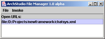
Instead of using the bootstrap, we could start the architecture using ArchStudio 3 directly. To do this, we start ArchStudio 3, then open the chatsys.xml description in the file manager:
Then, we can invoke the AEMDriver (Architecture Evolution Manager GUI Driver) from the Invoke menu:
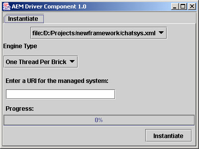
And click "instantiate" (the default parameters are fine).
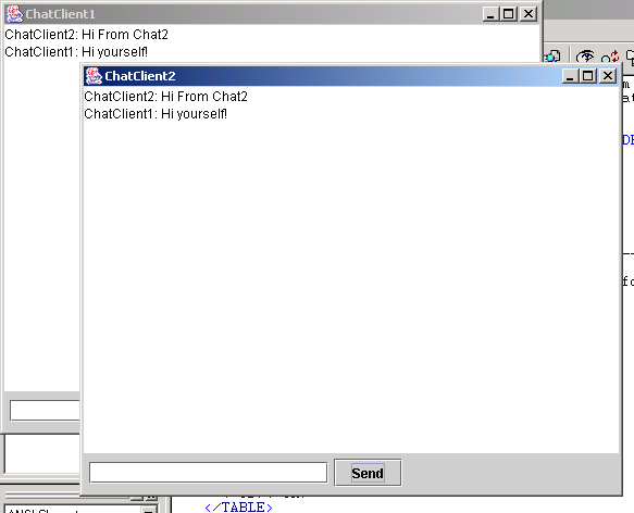
At this point, whether we have used the Bootstrapper or AEMDriver, two windows should appear in the 0,0 position on the screen, as seen here (after slight repositioning):
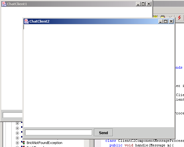
Typing a message into one window will make it appear, prefaced by the component ID, in both windows:
Conclusions and Wrap-Up
In this walkthrough, we covered:
- Describing an architecture using the Structure and Types xADL 2.0 schema.
- Reusing existing c2.fw components (the Bus connector)
- Creating two custom c2.fw components to implement part of our architecture.
- Instantiating a working architecture using the ArchStudio bootstrapper.
Comments? Questions?
Comments or questions on this tutorial should go to Eric Dashofy.